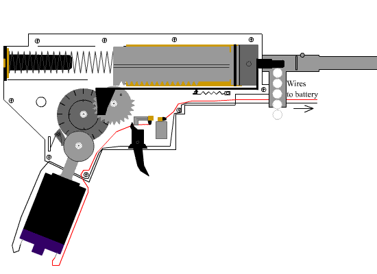
⇨ DIRECTION CONTROL : RATCHETS
 A ratchet is a mechanism that controls the direction of motion. Only allows motion in one direction.
Some ratchets are reversible, they can turn to both directions. We find them in watches, cable-tensors and elevator brake systems.
A ratchet is a mechanism that controls the direction of motion. Only allows motion in one direction.
Some ratchets are reversible, they can turn to both directions. We find them in watches, cable-tensors and elevator brake systems.
⇨ SPEED REDUCTION : BRAKES
Brakes use friction to reduce speed, and they are activated by levers. The levers transmit force to an output receptor, which puts pressure on the wheel. This produces friction, that slows down the wheel.
There are 3 types:
♦ Disc brakes: It is connected to an axle. The disc has pressure thaks to the brake pads.
♦ Band brakes: A drum is connceted by an axle. A fexible band puts pressure on the outside of the drum. We use them in carriages and they depended on the strength of the driver.
♦ Drum brakes: A pair of brake shoes apply pressure to the inside of the drum.
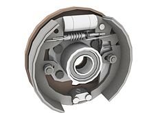 |
| DRUM BAKE |
 |
| BAND BRAKE |
Some mechanisms convert linear motion into rotary motion, but the most are reversible. They also transform rotary motion into linear motion.
The linear motion can be undirectional or reciprocating, that alternate from one side to the other.
⇨ ROTARY-LINEAR TRANSFORMATION
➜ Wheel
Wheels are important parts of bicycles and they let us move more easily because they reduce our contact with the ground and decrease friction, but if there isn't enough friction, the wheels can slide out of control.
A wheel moves forward a distance that is equal to its circumference, so we need less force with larger wheels and they move more quickly.


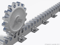
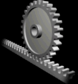
➔ Rack and pinion mechanism
This mechanism transforms rotary motion into linear motion as a wheel an it has two parts. The rack is a bar with many teeth and the pinion is a gear with teeth that interlock with the rack. The pinion rotates and the rack moves in linear direction. It can be reversible. We use them for sliding dors, conveyor belts...

➔ Nut and bolt mechanisms
As a rack and pinion, this mechanism has two parts: a bolt or shaft with a spiral groove and a nut that turns around it. We can turn and tighten the nut or the bolt in order to holds things together. We can use this mechanism to lift loads because it acts as a reducing system. Ex: scissors jacks, water tap mechanisms, screw-top bottles...


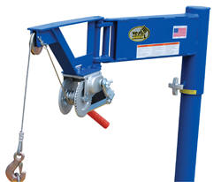
➔ Winch and crank mechanism
A winch is a cylinder that rotates around a horizontal axis. We attach a rope to the winch and to a load, and we turn the crank to rotate the winch. The rope rolls up and lifts the load. The crank increases the force and the winch transforms rotary motion into linear motion. This is proportional to the ratio between the radious of the crank and the radius of the winch.
We find this mechanism in construction cranes and in the mechanism that raises window blinds in our homes.


⇨ RECIPROCATING ROTARY-LINEAR TRANSFORMATION
 The pedal of a bicycle transforms the reciprocating movement of our legs into continuous. Some mechanisms work in the opposite way.
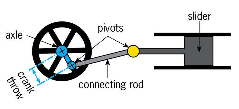
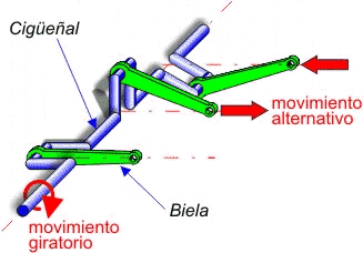
➜ Crank and rod mechanism
This mechanism was important for the fist steam engines. Today we find cranks and rods in internal combustion engines, as well as windscreen wiper mechanisms.

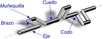
➔ Crankshaft mechanism
A crankshaft mechanism is formed by multiple rods connected to one shaft. The rods are connected to cranks and the cranks are connected to the crankshaft.
This mechanism can synchronise the movements of various parts. We use them for sewing machines.

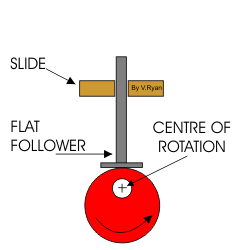
➔ Cam mechanism
A cam is an irregularly shaped device that rotates on a shaft. When the cam rotates, it pushes a bar called follower, that can move other parts and it can turn a switch on and off.
If we put multiple cams on one shaft, form other mechanism called camshaft, that makes the same function of a crankshaft. We can find them in toys, automatic tools and combustion motors.
Some cams are circular, but with an axis of rotation that is off-centre. These are called eccentric cams because they rotate in an irregular way. We can find them in sewing machines.
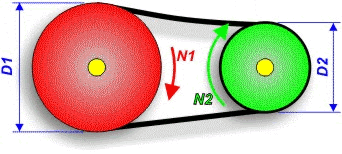
Rotary transmission systems put two rotating elements into contact. These mehanisms have two purposes:
⇸Transferring rotary force from an input location to another location.
⇸Changing the rotary speed by using rotating elements of different sizes.

These mechanisms keep the same speed ratios, but each one offers a different advantage.
⟶ CHANGES IN SPEED
♦ To increase the speed of a rotary system, we must transmit motion from a larger element to a smaller element, but when we increase the speed we also decrease the rotary force, or torque.
♦ If we want to decrease the speed of a rotary system, we must transmit motion from the smaller element to a large elemnet, and at the same time, we increase the torque.
♦ If both elements are the same size, the torque remains constant, and the rotary force will also remain constant.


⟶ SPEED RATIOS
When we have an increasing speed system, the smaller wheel rotates more quickly than the larger. This differnce in speed depends on the size of the elements. If the smaller wheel is five times smaller, it rotates five times faster. This happens because the smaller have to cover the same linear distance as the big wheel does in one rotation.
This relationship called the ratio of transmission, is inversely proportional to their sizes.
The operation is N square divided by n = d divided by D square.
 If we want to calculate the size ratio of wheels or pulleys, we compare their diametres, radius or circumference. In the case of gears, we compare the numbers of teeth (Z) that each gear has.
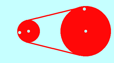
⟶ BELT DRIVES AND GEAR TRAINS
If we want to calculate the size ratio of wheels or pulleys, we compare their diametres, radius or circumference. In the case of gears, we compare the numbers of teeth (Z) that each gear has.
⟶ BELT DRIVES AND GEAR TRAINS
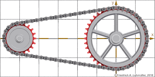
A belt drive is a system of pulleys connected by belts and each belt connects a pair of pulleys, so they turn together.
To calculate the ratio of transmission between the fist element and the last element, we must multiply the ratios of transmission of the first pair of wheels and the second pair.
The operation is N to the power of four divide by N = D multiplying by D cube divided by D square multiplying by D to the power of four.
⟶ CHANGES IN DIRECTION AND ROTATION
We can use various systems to change the direction of rotation or the axis of rotation a belt drive. We can also vary the distance between the wheels.
Gear drives require special parts to make these changes. We use diffrent types of gears when two axes are parallel, perpendicular or crossed.


In some gear mechanisms, several cogs or teeth intelock at the same time. These mechanisms are more precise and they transmit more rotary force , or torque.
⟶ WORM DRIVE
A worm drive reduces the speed of a rotary system very effectively and it has two parts; a worm shaft and a worm gear. We use them for tuning the strings of a guitar, for elevator mechanisms and for speed reducing systems. Each shaft has two, three or even more grooves, and each one interlocks with one tooth.
When the worm shaft makes one rotation, the worm gear moves forward one tooth for every groove on the shaft.
This tipe of mechanisms use liinear motion input to poduce linear motion output. We use them to transmit force.
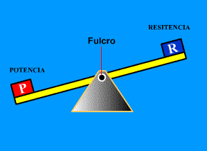
🔘LEVERS
Is a rigid bar that turns around a point called a fulcrum. In the lever can act some forces at the same time. Each force produces a torque, that is:
Torque = Force x Distance
The Law of the Lever says that the action of the forces on opposite ends of a lever are equal. So, the lever is in equilibrium.
F x D = R x r
F is the froce, d is its distance from the fulcrum, R is the resistance that we want to move and r is its distance from the fulcrum.
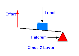
⊚CLASSES OF LEVERS
We can divide the levers according to the locations of the fulcrum, force and resistance.
🔸Class 2 increase the force that we apply. The resitance is between the fulcrum and the force (d > r)
🔸Class 3 increase the distance that the end of the lever moves. The force is between the fulcrum and the resistance ( d < r)
🔸Class 1 can do both of those things. The fulcrum is between is between the force and the resistance.

Brake levers
Brake levers decrease speed, such as bycicle brakes. They pull on cables and the cables activate the brakes on the wheels.
A hand crank
These levers have two parts. The first is connected to a rotating shaft and the other forms a handle. We use them to apply force at a distance from the axis of the shaft. It is a Class 2 lever, so they cumply with the Law of the Lever.
Bicycle handlebars
They work like a crank. If we put the hands at the ends of the handlebars, they are easier to turn, however if we put the hands in the midle, will happen the opposite.
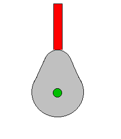
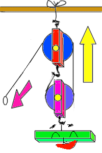
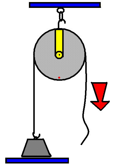
🔘 PULLEYS AND COMPÒUND PULLEY SYSTEMS
In a system of pulleys, the equilibrium between the forces depends on the path that the rope follows.
⊚ PULLEYS
A pulley is a wheel that rotates around an axis and had a groove. If we have wheels with ropes, belts or chains, we can lift objects with less effort. There are two types:
Fixed pulley: The forces are equal because the rope moves the same distances on both sides. It's easier to lift a weight if we use the gravity and our own weight, by pulling down.
F = R
Movable pulley: The rope follows a double path around the pulleys. We need half the force for lift a weight as with a fixed pulley.
F = R/2
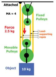
COMPOUND PULLEY SYSTEMS
It's a combination of fixed and movable pulleys, and it's also called a block and tackle system. If there are more pulleys, less effort we need. There are some ways to combinate them:
Vertical system } F = R/2 x n
Horizontal system } F= R/2 x n
Exponential system ➡F = r/2 n
There are block and tackle system without pulleys, such as rock climbers use carabiners. Some pulley systems are complex, and it is difficult to count movable pulleys. However, we can count how many times the rope goes up and down and use the equation F = R/U.


